The purpose of this week’s field post is to discuss the
process involved in georeferencing and mosaicking aerial imagery, in Arc Map,
that was obtained through balloon mapping (balloon mapping is discussed in
further detail in the blog post titled “Field Activity #3: Construction of
Field Mapping Equipment”).
Methods
Importance of Good
Quality Images
Before the georeferencing process can begin it’s necessary
to look through images that were obtained to find ones that will work well.
This includes finding images where the shot is perpendicular to the ground
(images 1 and 2), images that can overlap one another, and images that are not
blurry (image 3). These factors are important for several reasons including, shots
that are perpendicular to the ground will have less distortion in the center of
the picture compared to the edges.
Therefore when you overlap several pictures together they will depict a
realistic view of the ground. When the
camera is not parallel to the ground the images will be very distorted,
therefore the do not depict a realistic view of the ground. Images that are
fuzzy or not clear will also not depict a realistic view of the ground.
Image 1: Camera shot
that is perpendicular to the ground

Images that are perpendicular
to the ground will have less distortion in the center of the picture so they
will work the best for depicting a realistic view of the ground
Image 2: Camera shot
is not perpendicular to the ground

When the camera is not
perpendicular to the ground the images will be very distorted, therefore not
depicting a realistic view of the ground
Image 3: fuzzy or not
clear image

Images that are fuzz,
or not clear will also not depict a realistic view of the ground
Images 4 - 13 are the images I chose to use.
Image 4: Image chose
for georeferencing in my first mosaic

Image 5: Image chose
for georeferencing in my first mosaic

Image 6: Image chose
for georeferencing in my first mosaic

Image 7: Image chose
for georeferencing in my first mosaic

Image 8: Image chose
for georeferencing in my first mosaic

Image 9: Image chose
for georeferencing in my second mosaic

Image 10: Image chose
for georeferencing in my second mosaic

Image 11: Image chose
for georeferencing in my second mosaic

Image 12: Image chose
for georeferencing in my second mosaic

Image 13: Image chose
for georeferencing in my second mosaic

To begin the georeferencing portion of the activity I first
started a new project in Arc Map. I then opened the georeferencing tool bar
(image 14). Next, I brought in the control points feature class. This feature class was created by 3 students using 3 different types of GPS units. This was done
to provide ground control points to georeference too. I brought this feature
class in first because it set the data frame to UTM 15N through Arc Map’s
Project on the Fly feature. Next, I brought in the aerial image of the campus
location that was provided for us by our professor. Then I brought in group 5’s
feature class. This is a polygon feature class that was created by 2 of the
students in the class who took the initiative to divide campus into 6 areas so
each group could focus in one main area. This allowed for better use of time
and accuracy as the area we all had to cover was much smaller and people weren’t
all mapping the same area or leaving an area out. Finally, I brought in the
first image I wanted to georeference.
Image 14: Location of
the “Georeferencing” tool bar

1) To begin georeferencing I zoomed into the area I would be
georeferencing to on the aerial photo, with in group 5’s designated area.
2) Then, I made sure the image I was georeferencing was
selected in the georeferencing tool bar drop down box (image 15).
Image 15: Selecting
the correct image to be georeferenced in the georeferencing tool bar drop down
box

Image 16: Selecting “Fit
to Display” from the georeferencing drop down menu

Image 17: Image fit
within the display extent zoomed into

Image 18:
Georeferencing tools used to rotate, shift, and scale the image being
georeferenced

Image 19: Image
rotated, sized, and moved to best fit the area

Image 20: Determining
placement of control points

Image 21: “Add Control
Points” selected from the georeferencing tool bar

Image 22: Adding
control points from the image I’m georeferencing to the aerial photo

Image 23: “Update
Georeferencing” selected from the georeferencing drop down menu

Image 24: Exporting
the georeferenced as a raster file

Image 25 depicts my images after they were all georeferenced
and exported.
Image 25: Images after
being georeferenced and exported

Image26: Location of “Mosaic
to New Raster” tool in the tool box

Image 27: How to fill
out the “Mosaic to New Raster” tool

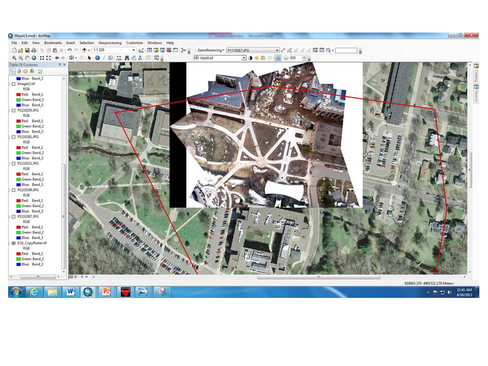
Image 28: Final
completed mosaic

Image 29: Location of “Effects”
tool bar

Image 30: Location of “Swipe”
tool in “Effects” tool bar

Image 31: Using the
swipe tool to check my mosaic in relation to the aerial photo
Overall, georeferencing is easy and difficult at the same
time. The method itself is easy to perform, although it can be quite time
consuming. However, making the overall mosaic line up perfectly was very
difficult. As we discussed earlier, the center of an image taken when the shot
is perpendicular to the ground is less distorted than the outside of the image.
This is because of the angle at which the shot is taken. Because of this, it’s
safe to use about the center 60% the image for georeferencing. However, the UWEC
campus, which we’re creating an aerial map of, is under construction. Therefore,
there are no updated aerial maps available as the reference, or ground point,
map. Because of this our group had to rely solely on the ground points taken by
the GPS units to georeference our data because our area to mosaic was located
where a building has been removed and sidewalks have been added. This made georeferencing
our data extremely difficult. The majority of the time we had no clue if our
georeference lined up well or not because there were no sidewalks in the old
aerial photo to compare them to. I did make a new map of the area of campus
located over Phillips Hall (image 32) just to test my strategy. With this map I
used georeferenced my control points to ground points, and tops of buildings. I
also used the outside of my images, and a larger amount of control points; sometimes
up to 30 or 40 control points on one image. Overall, this image turned out ok,
but I know it was really distorted due to my manipulation of the photos.
Image 32: Second
attempt at a mosaic using sloppier methods to compare to my original mosaic

With this activity I learned the importance of very accurate
ground control points. Without accurate ground control points it’s nearly
impossible to create an aerial map that depict the landscape below. I also
learned that no matter how much you want to make something turn out good it’s
never a good idea to manipulate things to work for your benefit. Had I used the
second map I created it may have had significant implications down the road to
someone who may have tried to use it for something important. For example, if
someone planned on using it for measurement the measurement would probably be
off by a lot for them.
I also learned that it is important to have your camera on
the right setting for the intended purpose of your field activity. We
accidentally had our camera set on “normal” mode instead of “scenery”. This
resulted in the camera being out of focus a lot of the time. This isn’t good because
it’s important to have as many good pictures as possible to create a realistic
aerial map.
No comments:
Post a Comment